
Fox Blocks | Step-By-Step Installation Guide
Printable Step By Step Instructions:
Fox Blocks Quick Product Install and Tech Guides
- Fox Block Tech Doc-Interlock
- Fox Block Contractor Qualify Form
- Fox Block Tech Doc-Basic Estimate
- Fox Block Tech Doc-Cross Sec-4
- Fox Block Tech Doc-Curb Block
- Fox Block Tech Doc-End Sizing
- Fox Block Tech Doc-Energy Stick
- Fox Block Tech Doc-Ext Corner
- Fox Block Tech Doc-HV Clip
- Fox Block Tech Doc-lineup
- Fox Block Tech Doc-Man Hour
- Fox Block Tech Doc-TBlock
- Fox Block Tech Doc-True Cost
- Fox Block
- Fox Blocks Installation Guide
- Fox Blocks 22 foot 8 inch sample wall on footing
- Fox Blocks Construction Site Check List
- Fox Blocks Product Dimensions and Data
- Fox Blocks Shallow Frost Footings
- Fox Blocks Tech Doc Below Grade Walls 2010
- Fox Blocks Technical Code and Testing Data Cutsheet
- Fox Tiltup 1440 Cutsheet low res
- Shallow Frost_Stem Fox Block
Fox PDF JPEG Block Views
- 3d views radius block 2 ties – 8 ft
- 4 T block assembly long
- 4 T block assembly short
- 6 Corner block assembly v2 1-19-10
- 6 Corner block assembly v2
- 6 inch corner block v2 Extended
- 6 inch corner block v2
- 6 inch extended corner block v2
- 6 inch radius block 2 ties – 5 ft
- 6 inch radius block 2 ties – 6 ft
- 6 inch radius block 2 ties – 7 ft
- 6 inch radius block 2 ties – 8 ft
- 6 inch radius block 2 ties – 9 ft
- 6 inch radius block 2 ties – 10 ft
- 6 inch radius block 5 ft 031808
- 6 inch radius block 10 ft 032108
- 6_corbel_ledge
- 8 Corner block assembly v2
- 8 Corner block assembly v2
- 8 Corner extended block assembly v2
- 8 Corner extended block assembly v2
- 12 Corner block assembly
- 12 Corner block assembly
- 12 Straight block assembly
- 12 Straight block assembly
- T block 6 4 assembly long
- T block 6 4 assembly short
Fox Blocks Full Technical Manual
- Fox Blocks PM Contents
- Fox Blocks PM Section 7 Green
- Fox Blocks PM Section 6 Compatible Products
- Fox Blocks PM Section 8b Glossary
- Fox Blocks PM Section 9 1440
- Fox Blocks tPMt Appendix A_1 MSDS
- Fox Blocks PM Section 2 Product
- Fox Blocks PM Section 1 Intro
Planning and Preparation to Build
Plan the job from the start for a fast profitable build. A well planned project will work much more smoothly and save you, the contractor, from unnecessary additional costs.
Have the materials and tools at the site. Have adequate bracing to do the project. Plan good access for the concrete pump and ready-mix trucks. See Appendix A for Safety Guidelines associated with concrete placement using a concrete pump and ready-mix trucks. Check and align the walls prior to placing the concrete. Align and plumb the walls again just after the pour.
Information needed before the start of construction to plan the build:
- Building plans,
- Rebar specification for the walls, the lintels and around openings,
- Specification for the concrete,
- Rough stud opening measurement requirements for the window and door openings,
- Anchor bolt specification and onâ€center spacing (in hurricane prone areas, high wind areas, and regions having a high seismic design category, there may be additional requirements to connect the floors and roofs to the walls).
The key planning steps are:
- Plan for job safety,
- Complete an accurate takeoff and order sufficient Fox Block,
- Draw a wall crossâ€section elevation view in advance and determine where the coursing will be, the window openings, lintels and the top of the wall. This exercise will assist in planning the build,
- Pour footings level to + or – ¼ inch,
- Plan to have the necessary tools at the site,
- Plan to have adequate crew,
- Designate a space on site for the storage of the Fox Block forms. Frequently it is near the center of the building being constructed where access will be easy during the construction of the walls,
- Mark out the wall on the footing or slab and then mark where doors, windows, utility services, etc… will go. This will enable you to easily visualize the layout, identify potential difficulties prompt you to plan of how address these items.
- Schedule the pour so you have adequate time to inspect the Fox Block walls with the forms empty and confirm they are ready and all the bracing and support is in place for the concrete.
- Prior to the pour, walk through the site and complete a checklist to confirm the walls are ready for the concrete.
- Order the concrete pump to come a ½ hour before the concrete so it has adequate time to set up,
- Request the concrete pumper to bring a double 90 degree or reducer to 4inch and a short length of 4ft flexible hose, to be added on the end of the pipe to slow the velocity of the concrete during placement,
- Plan to have a vibrator on site (recommended 1 Horsepower with a head 1 inch or less in diameter), confirm power source and have adequate extension cords,
- Ensure there is adequate access for the concrete pump truck and ready-mix trucks and make sure there is a location for the trucks to clean out,
- Remember to plumb and check the alignment of the wall immediately after the pour is complete,
- Do not backfill against the ICF foundation walls until the floor system has been installed or adequate lateral support has been provided. The temporary bracing and alignment systems designed to brace and align the walls during stacking of the Fox Block ICFs and placement of concrete are not designed to provide adequate lateral support to resist the forces imposed by the backfilled soil.
Tools and Materials List
In addition to the usual tools a contractor would have, the following is a list of tools recommended to have on site while assembling Fox Block walls. Having these items on the project site will facilitate an easier build:
- Wall bracing and alignment system including:
– Screws to secure the strong backs (a.k.a uprights) to the Fox Block ICF’s- Fasteners to anchor system to substrate,
– Scaffold planks and other lumber if required for guard rails, mid rails, toe boards and bearing planks,
– Fasteners to secure scaffold planks and guard rails in place, if required.
- String line or chalk line
- Zip tie or wire ties
- Rebar bender/cutter
- Rebar ties
- Rasp
- Foam gun and refills
- Pruning saw & key hole saw
- Construction laser level
- Mason’s level
- Fiber tape
- Waterproof markers
- Cordless drill
- Stepping stools and step ladders
Additional items recommended having on site at the time of the concrete pour:
- Safety equipment: hard hat, safety vest, safety glasses, rubber gloves, wash water & mask.
- If elevations require: fall restraint and/or fall protection equipment
- Internal vibrator: recommended 1 horsepower and with maximum head diameter of 1 inch or less. Also confirm power source and have adequate extension cords.
- Concrete pump special equipment, 4inch reducer and a length of 4ft hose to slow the velocity of the concrete.
Handling and Storage of the Fox Blocks ICF on Jobsites
General Guidelines
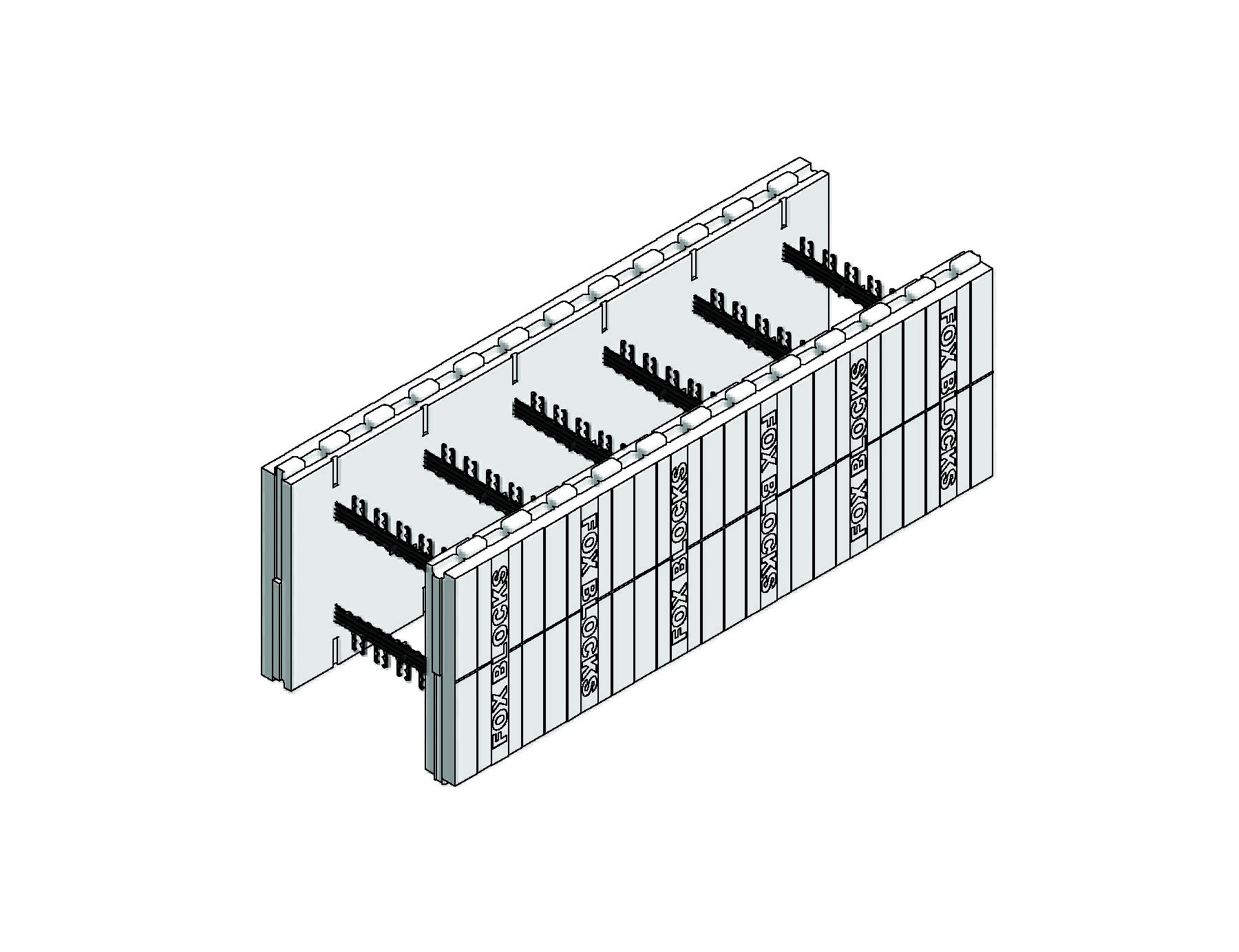
There are several recommendations to effectively handle and store Fox Block forms on site. Unlike most ICF systems the consistent 2-5/8″ EPS panel thickness of all the Fox Block forms means Fox Block ICF can better resist damage from handling compared with other ICF’s. Further the Fox Block straight forms arrive on disposable corrugated sheets in small bundles of 6 to 12 forms wrapped or banded together. This provides further jobsite protection. Several suggestions are:
- If transporting Fox Block ICF’s on an open trailer position the bundles so the air can pass through the forms to reduce drag, and ensure they are well secured to avoid damage from the strapping material
- Unloading can be accomplished manually or using lifting equipment
- The bundles of Fox Blocks can be easily moved by two people
As a general guideline, Fox Block ICF’s should be stored on site in a location which has easy access for the trucks delivering the forms and easy access by the construction crews. On sites where the forms will be stored for several days or weeks, it is recommended that the location be secure. The forms should be protected from prolonged exposure to ultra violate (UV) radiation, mud, winter ice and snow, because keeping the Fox Blocks clean and not having material accumulate in the interlock will assist the crew to stack the Fox Blocks walls quickly.
It is important to store the forms in a location on the job site where they are easily accessible by the crew and at a location where they are safe from damage from other onâ€site activities.
Outside storage
If Fox Block ICF’s are be stored outside it must be recognized that the expanded polystyrene (EPS) left exposed to sunlight will start to yellow after approximately 2 months. Fox Block ICF’s are shipped in bundles with corrugated lids, held in place with shrink-wrap or strapping, to protect the forms from sunlight. However this protection may become damaged on site causing potential exposure of the plastics to UV radiation. The yellowing and subsequent chalking of the foam is not of major concern, but must be removed by washing or brushing prior to application of any product which is to adhere directly to the surface of the EPS (i.e., peel and stick waterproofing or textured acrylic finish systems (TAFS)). In situations where it is anticipated that the Fox Block ICFs will be in outside storage for more than 3 months, protection from sunlight is recommended. The forms can be stored under a roof or covered with dark tarpaulins.
Also when Fox Blocks are stored outside efforts must be taken to keep debris, mud, and in winter ice and snow, from accumulating in the interlock.
Residential Constructions Sites
At residential construction sites, frequently the bundles of Fox Blocks can be placed in the center of the building site at least 10 feet away from the location of the walls. This provides excellent access to the Fox Blocks by the crew while maintaining adequate space along the walls for construction of the walls and erection of the bracing and scaffolding.
Commercial Construction Sites
On commercial construction sites the Fox Blocks forms are best stored in an area where they are both easily accessible for transfer to the walls for construction and away from activities which could cause damage. Frequently the forms are stored in a secured location on site and then transported to the construction location along the walls as needed by the crews.
Hot Weather
In hot weather, the more intense sunlight can accelerate the yellowing and chalking of the foam plastics if it is left exposed. This can take place in less than 2 months if Fox Block ICF’s are left exposed to sunlight. Contractors are recommended to take the precautions as set out in the paragraph on outside storage. Also, for concrete placement, see ACI document 305, Hot Weather Concreting.
Cold Weather
In cold weather remember to place the Fox Block ICF’s on plastic sheeting or other materials so they do not freeze to the ground or slab. Likewise, cover them so that ice and snow does not accumulate in the interlock. Also, for cold weather concreting see ACI document 306, Cold Weather Concreting, and PCA has published a document Cold Weather Construction of ICF Walls which is a recommended reference.
Footings, Slabs and Grade Beams
Footings can be formed footings, slabs on ground, or grade beams supported on piles. All of these are viable footing systems provided they have been properly designed and engineered as required by local soil conditions and building department requirements. If site specific structural engineering is required it is the responsibility of the owner. The footing or slab must be level to within + or – ¼ inch.
Step 1: Following excavation or other site preparation as required, layout the footing location in accordance with the plans and specifications.
Step 2: Ensure accurate 90 degree corners by using one of the following methods:
- Equal diagonal measurements ( assuming rectangular layout)
- 3-4-5 triangle
- Surveying
Step 3:Install footing forms and rebar as required by the plans, specifications or applicable building code. This includes dowel placement and spacing.
Step 4: Place caps on all dowels once they are installed for safety compliance.
Step 5: Place concrete into the formwork as per ACI 309 & 318 specification, and level to + or – ¼ inch. If required by specifications, project drawings or applicable building code install a keyway.
Note:
i) If step footings are required due to a sloped building site the ideal increment is 16 inches. This is the recommended step height as it reduces the labor required by matching the height of the Fox Blocks forms. A step height of 8 inches can be used but the Fox Block forms will need to be cut in half. It is possible to achieve step heights of 4 inches by using Fox Block height extenders.
Fox Block ICF First Course Wall Layout
It is important to layout the Fox Block ICF wall on the footing or slab as specified in the building plans or engineering drawings. Accurate wall layout is key to constructing a complete and profitable project.
Step 1: Mark out the exterior of the surface of the Fox Block walls on the footing or slap using a chalk line.
Step 2: Check to ensure the 90 degree corners are accurate by using one of the following methods:
- Equal diagonal measurements
- 3-4-5 triangle
- Surveying
Step 3: Mark on the footing or slab the location of the doors, windows and any other penetrations in the wall. Then a guide board or metal channel can be fastened to the footing or slab along the chalk line to guide the placement of the Fox Block forms. If only using a chalk line a suggestion is to use clear lacquer to protect the chalk line from being washed away by rain.
Step 4: Place the first course of Fox Block forms starting at one corner and working around the wall.
Step 5: Verify that the outside face of the Fox Block walls line up with the overall building dimensions as specified on the plans.
Step 6: Tie the fox Blocks in first course together end to end using zip ties or wire.
Step 7: Install the horizontal rebar as specified.
NOTE:
i) To achieve accurate 45 degree corners use Fox Block 45 degree corner forms
ii) Wall layout of radius or other corner angles can easily be achieve with Fox Block ICF
iii) If dowel bars were not installed into the footing and they have been specified, they can readily be installed once the first course is in place by drilling and using epoxy adhesive.
Placement of the Second Fox Blocks Course
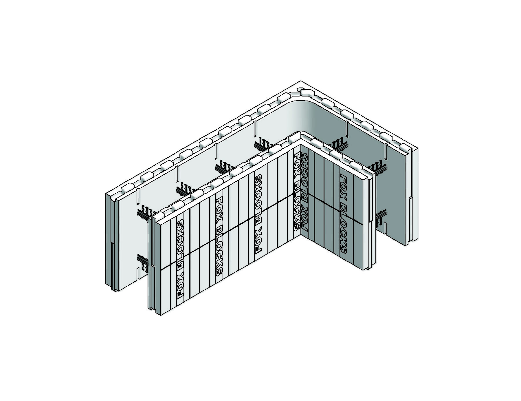
Step 1: Starting at the original corner, place a corner form in the reversed direction, with the long end extending in the other direction compared to the first course. This will create the offset or running bond.
Step 2: Fasten every corner form end-to-end to the adjoining straight forms with zip ties and adhesive foam in necessary. We recommend zip tie connecting the first and second corner forms together for secure alignment of the Fox Blocks ICF wall during construction.
Step 3: Continue setting the forms in place around the wall working in the same direction as was taken with the first course.
Step 4: Each Fox Block form must be fully seated into the forms below to minimize settling at the interlocks during placement of the concrete.
Step 5: It is preferable that the cross ties (marked FOX BLOCKS) line up vertically, however this may be difficult to achieve with all building dimensions.
Step 6: After the second course is in place install the horizontal rebar as specified.
Step 7: After stacking the second course confirm the wall is straight and level. If it is not level make adjustment by shimming or trimming the bottom of the wall as needed.
Step 8: After confirming the wall is straight and level use foam adhesive to secure it in position to the footing or slab.
NOTES:
i) When stacked vertical joints occur, these are where the joints between the forms stack one on top of the other, addition support is required. This is achieved by screwing horizontally across the joints at each course a 1x4 or 1x3 wide strip cut from plywood.
ii) Similarly, vertical joints are less than 8 inches apart or if due to vertical joints the distance between webs is greater than 8 inches, additional form support is required.
iii) It is important to note at this point that the wall pattern has been established. Course number 1 will be the pattern for all odd numbered courses (3, 5, 7, etc.). Course number 2 will be the pattern for all even numbered courses (2, 4, 6, etc.).
Placement of third and higher courses of Fox Block ICF
Continue building the Fox Block walls one course at a time as was done for the first and second courses.
Step 1: Fasten every corner form endâ€toâ€end to adjoining straight forms using zip ties or adhesive foam.
Step 2: Install the bracing and alignment system after the third course is in place.
Step 3: Install Durawall wire at the mid height of the wall and again at the top course of the wall. If there are windows in the wall the mid height Durawall can be installed in the course immediately below the windows as this assists keeping the walls straight.
Overlap the lengths approximately 10 inches. Align the points of the triangular pattern of the Durawall directly above the Fox Blocks crossâ€ties. Durawall should be held back form corners approximately one foot in each direction. Durawall should not be used when constructing curved walls.
Step 4: After each course is placed install the required horizontal rebar as per code requirements or engineering specifications. Please note that is some applications the horizontal rebar may only be required in every other course.
Step 5: In the top course secure forms endâ€toâ€end to maintain building dimensions.
Step 6: When the top course is in place, install the vertical rebar as by placing it down through the horizontal rebar. It must be installed as per the engineering drawings or building code requirements.
Step 7: Secure top course to the forms below on both sides of the forms and endâ€toâ€end with zip ties. This is to prevent the forms from being displaced or knocked out of alignment during concrete placement.
Step 8: Install appropriate size pipes or tubing to provide penetrations for all utility services and exhaust and dryer vents.
Step 9: If additional stories are planned, the interlock needs to be protected prior to concrete placement. This can readily be done with tape or a metal channel cover to prevent concrete splatter from accumulating in the interlock.
Step 10: Check the building dimensions. Check the corners and along the walls to confirm they are plumb.
Step 11: Check the walls to ensure they are straight by placing a string line at the top course offset from the wall ¾inch using pieces of wood placed in the corners. Check for straightness by running another ¾inch piece of wood between the string line and the wall.
Notes:
i) When vertical joints and less than 8 inches apart or if due to vertical joints the distance between webs is greater than 8†additional form support is required. This is most frequently achieved by screwing 1x4 or 1×3 inch wide strips cut from plywood horizontally in the area and attaching the additional support to two webs either side of the vertical joint(s).
ii) If you need to stack the forms so the vertical joints line up additional form support is required at these stacked joints.
iii) At window and door openings, when placing place rebar maintain minimum of 2inch space between the rebar and the buck material.
iv) The corner forms have additional plastic reinforcement embedded in the foam to provide added strength and furring opportunity for attachment of cladding and exterior finishes at the corners. The forms also have a hole located vertically near the tip to allow a length of rebar or PVC tubing to be pushed through multiple courses to tie the wall corner together.
ICF Wall Bracing, Alignment & Scaffolding Systems
ICF wall bracing alignment & scaffolding systems are used to provide temporary bracing of the Fox Block ICF walls to keep the walls straight and plumb during concrete placement and provide a safe work platform for the placement of concrete. Practice job safety, respect all warning and limitations of the system which is selected for use on your job. Typically the wall alignment system is installed on the inner side of the Fox Block walls being constructed.
Generally each alignment unit consists of a vertical upright steel channel with slots for attaching screws to the cross ties of the Fox Blocks forms, a diagonal with a turnbuckle and a scaffold bracket.
After installing 2 to 4 courses of Fox Block forms (depending on wind and other conditions), attach the alignment system to Fox Block walls with screws to the cross ties.
Place bracing and alignment units within two feet of each corner and one every 4 to 6 feet thereafter in accordance with OSHA (American) requirements or OHSA (Canadian) requirements. Alignment units should also be placed on either side of every door and window opening.
Step 1: Attached the upright steel channel to crossâ€ties with a screw (#10 hex head is recommended) in each course of Fox Block forms. The screws should be snug but not tight. Always place screws near the top of the slots to accommodate settling during concrete placement. When specified, attached the base of the upright to the substrate with adequate anchorage.
Step 2: Attach a turnbuckle arm to the upright with a bolt and then secure the other end to the substrate with adequate anchorage, as specified. If anchoring into soil additional care must be taken to provide sufficient anchorage.
Step 3: The scaffold bracket is then mounted on the upright at the specified location.
Step 4: Place the appropriate scaffold planks and guard rails and toe boards as recommended by the manufacturer and compliant with OSHA requirements in the USA and OHSA requirements in Canada.
Step 5: Prior to concrete placement make certain walls are aligned and plumb, or leaning slightly towards the braces. The wall must not lean away from the braces.
Step 6: A string line must be used to achieve straight walls.
Step 7: Just before and after concrete placement the diagonal turnbuckle arms are used plumb the wall and to adjust wall straightness to the string line.
NOTES:
i) It is the responsibility of the contractor to meet the applicable labour safely regulations. Generally these are OSHA requirements in the USA and OHSA in Canada
ii) For other bracing alignment and scaffolding systems see the respective manufactures instructions for use.
Window and Door Openings
It is recommended that bucks be built ahead of time and be on site and ready for placement in the walls at the appropriate time in the construction of the Fox Block ICF walls. The bucks are used to hold back the concrete and in most cases stay-in-place permanently providing a fastening surface for the installation of windows and doors.
Bucks can be either the Fox Blocks EPS Buck (or equal) or fabricated out of treated wood with 2X12″ or plywood having 2x4’s running the length of the buck along both sides.
Step 1: Build bucks ahead of time and have on site for Fox Blocks build. Make sure the bucks are assembled with the correct rough opening dimensions for the window or door assembly specified for the openings.
Step 2: Install bucks in each location where the plans call for an opening. Check both the elevation and the location in the wall to confirm it is placed in the correct location.
Step 3: Provide a system of anchorage to the concrete in the Fox Block wall. Fox Block Buck has perforations which become embedded in the concrete when it is placed and provide the anchorage. Wood bucks can be anchored with bolts or by driving long nails, spikes or carriage bolts through the wood into the concrete cavity to become embedded in the concrete.
Step 4: The bucks, after being placed in the Fox Blocks walls, should have internal bracing to support the jambs and header, to keep them plumb and level by providing adequate support to stop them from deflecting into the opening from the load imposed by the wet concrete during placement. This bracing can be achieved using 2x lumber or using one of the several systems available for this purpose. This bracing is removed after the concrete has cured.
NOTES:
i) When building wood bucks it is recommended that the bottom of the buck (the sill) be constructed with 2×4’s so that a space is left between the 2x4’s. Concrete can then be placed into the forms below the buck through this space.
ii) Also, when constructing wood bucks remember that untreated wood cannot be placed in direct contact with the concrete. Therefore the bucks must be constructed with pressure treated lumber or a moisture barrier must be installed between the concrete and the wood.
iii) When using pressure treated lumber ensure the anchor bolts and /or nails are compatible with the pressure treated lumber.
iv) When using proprietary buck systems and/or bracing systems refer the respective manufactures information for proper instructions for use of their product.
v) When placing concrete it is recommended that concrete be first placed under the openings though the holes left in the sill of the bucks. When using wood bucks, once the wall cavity in the Fox Blocks below the bucks have been filled and the concrete consolidated the middle 2×4 may be inserted into place in the middle of the sill of the buck.
vi) Bucks must be constructed to provide the necessary Rough Opening dimensions. This information should be available on the building drawings or from the window or door manufacturer.
vii) The internal bracing in the opening may be removed when the concrete has cured adequately. At this time if using wood bucks the 1×4 strapping may be removed.
viii) Please note that when windows and doors are installed into Fox Blocks walls attention to proper flashing detail is important. Correct installation of flashing, top caps, sills, proper caulking, etc., is needed to ensure that the weather barrier and air barrier are continuous and that water is directed to the outside of the walls. Fox Blocks recommend using a peel and stick flexible 30mil thick flashing.
Steel Reinforcement and Placement
Step 1: The steel reinforcement (rebar) must be placed as specified on the engineering drawings or as specified in the prescriptive ICF wall design in the applicable building code.
Step 2: Snap the horizontal rebar into the locking supports on the cross ties of the first course. As additional course are added to the wall place the rebar in each course as required. The rebar should be placed so that it alternates left and right of center on alternate courses of Fox Blocks.
Step 3: By staggering the horizontal rebar left and right a space is left for the vertical rebar to be lower from the top of the wall into position and be held in place by the horizontal rebar.
Step 4: Footing dowels and vertical rebar do two different tasks, the footing dowels are a shear members and the vertical rebar is a tension member. Because of this, a lap splice is not critical and not required in many areas. If you are required to provide a non contact lap splice, create 2ft tall rebar sleeves out of 1.5″ PVC pipe with a skill saw. Before stacking the forms place the sleeves over the vertical dowels protruding from the footing or slab. Then, when placing the vertical steel set the lower end of the vertical steel into the sleeves to secure them in close proximity of the dowels so the requirements of a non contact lap splice are met. (Some code inspectors do not allow these PCV sleeves, so check with the local building official before using. The alternatives are using sleeve cut from a steel pipe, or cut holes in the EPS and tie the rebar to the dowels and then replace the EPS and place strapping over the EPS patches to provide support.)
Step 5: Once the entire wall is stacked, lower into position the vertical rebar, between the horizontal rebar. Where sleeves have been placed over the dowels, drop the end of the vertical steel into the sleeves as appropriate.
Step 6: The vertical steel is held in position by the horizontal rebar, and the sleeves where required. Some jurisdictions require the top of the vertical steel to be secured. If this is the case tie the top of the vertical rebar to the top horizontal rebar.
Step 7: For reinforcement around openings and lintels, refer to applicable prescriptive design in the applicable building code or engineering design specifications. These specifications will include details for placement of steel around openings and in the lintel across the top including stirrups if required.
Step 8: Horizontal rebar placement at 45 degree and 90 degree corner locations should be bent and continuous for a minimum of 24 inches in each direction from the corner. This will require the use of preâ€bent corner bends or the ability to bend rebar on site.
Step 9: Lintel reinforcement is required above doors and window openings, where the opening is greater than 2 feet. Construct as specified in applicable building code or engineering drawings.
Notes:
i) For applications outside of the prescriptive design provided by several building codes, engineering structural design of the reinforced concrete wall cast in the Fox Block ICFs must be in accordance with ACI 318 in the US and CAN/CSA A23.3 in Canada.
ii) It is recommended that the vertical rebar be 2 inches shorter that the height of the wall. This will allow for an inset sill plate. The rebar can be pre-ordered cut to length or field cut.
iii) If rebar splices are required the codes allow the use of both contact and non contact lap splices.
Utility Service Penetrations
Utility services such as electrical service and vents can be accommodated by inserting and appropriate sized tube through the forms prior to concrete placement. Remember it is much easier to do this before the concrete is poured than to have to cut a hole through the concrete later.
Step 1: Determine the service penetrations needed and the size and location.
Step 2: Install the appropriately sized sleeves in the correct locations.
NOTES:
i) List of possible utility & service penetrations:
- Electrical main service
- Gas line
- Water
- Sewer
- Cable & telephone line
- Alarm system lines
- Dryer vent
- Water heater vent
- Furnace vent
- Bathroom and kitchen vents
- Central vacuum
- A/C line
- Kitchen appliance venting
- Pet door
- Hose bibs
ii) Remember sleeves that are too lightweight may be crushed during concrete placement.
Gables End Walls
To form a gable end walls cut the forms at the required angle and stack them in place. Install bracing as necessary. If it is anticipated that the wet concrete will flow out of the top of the forms due to the angle of the cuts and the slump of the concrete, fasten strapping along each upper outside edge of the forms and then fasten a strip of plywood on top of the sloped forms. This will contain the wet concrete. Remove the plywood and strapping when the concrete has hardened.
End Walls
In cases where a wall is to be terminated with no corner at the end of the wall, there are typically three different methods to achieve this: continuous EPS at the wall end, exposed concrete at the wall end and the wall ending with a wood buck. Each is described below in some detail.
In cases where the wall end is to be encased in EPS foam, EPS should be cut from EPS sheet stock of the thickness desired and inserted into the ends of the forms. Alternatively for 4″ and 6″ walls portions can be cut form a Fox Block form and inserted at the end of the wall. The end of the wall then needs to be supported with a temporary buck, typically treated 2x framing lumber. This buck needs to be tied back to the wall with strapping which is screwed into the 3 webs closest to the end of the wall. The strapping can be 1x4 cut approximately 18 inches in length or it can be cut from plywood 3ft wide. The buck should be braced at its base, every three feet going up the wall and at the top, to resist movement and transmit the formwork forces to the ground or supporting substrate.
In cases where the concrete is to be exposed a 2x buck should be used and held firmly against the ends of the panels of the Fox Block forms. Again, this buck needs to be tied back to the wall with strapping which is screwed into the 3 webs closest to the end of the wall. The strapping can be 1×4 cut approximately 18 inches in length or it can be cut from 1/2inch plywood 3ft wide. The buck should be braced at its base, at three foot intervals up the wall and at the top, to resist movement and transmit the formwork forces to the ground or supporting substrate.
And in cases where the 2x buck is to be left in place, it should be pressure treated lumber, or separated from the concrete with an approved moisture barrier applied to the side of the untreated lumber to be exposed to the concrete. The bucks must be anchored to the wall with approved anchors. In many regions nails/spikes/screws are acceptable; in other areas bolts are required. To anchor the buck with bolts, drill ½ inch holes on 2ft or 3ft on centers along the length of the buck. Once it is in position and prior to the placement of concrete 10″ carriage bolts or lag bolts are driven through these holes so their ends extend into concrete cavity to become embedded in the concrete. Prior to the placement of concrete the bucks need to be tied back to the wall with strapping which is screwed into the 3 webs closest to the end of the wall. The strapping is removed after the concrete has hardened. The strapping can be 1×4 cut approximately 18 inches in length or it can be cut from 1/2inch plywood 3ft wide. The buck should be braced at its base, every three feet up the wall and at the top, to resist movement and transmit the formwork forces to the ground or supporting substrate.
Alternatively one of the proprietary systems supplied by Fox Block Buck or LSL. All could be used to form the end of the wall. Please find their contact information in Chapter 6.
Radius Walls
Fox Block ICF has radius blocks in the 6″ wall thickness to build curved walls with a radius of 5ft, 6ft, 7ft, 8ft, 9ft, and 10ft. For curved walls with a radius of greater than 10 feet straight Fox Blocks can be easily modified with cuts on the inside panels as shown in the table below.
When building with the radius blocks stack up the radius blocks in a running bond manner so that the only vertical stacking joints are at the ends of the radius portion of the wall. Remember to apply additional support at these vertical joint (install 1×3 strapping, cut from ½inch plywood, across the vertical joints at every other course.) and use adequate bracing.
Please note horizontal rebar as specified in the engineering drawings must be bent to the appropriate radius to be inserted in courses of Fox Blocks.
Beam Pockets
Creating beam pockets in a Fox Block walls is easily done by using EPS to block out the portion of the wall where the beam pocket is needed.
Create a sacrificial form by cutting one or several pieces of EPS from scrap Fox Block forms or from EPS sheets or Styrofoam and position in the wall cavity to create a void in the concrete at the required locations. Remember to anchor it in place as it will tent to float when the concrete is placed around it.
Place the concrete in the wall. Give attention to not dislodge the sacrificial form, particularly during consolidation of the wet concrete. After the concrete has set this EPS can be easily removed from the wall leaving the beam pocket in the Fox Blocks wall.
Note: It is not uncommon for the structural beams (steel, wood and composite) to need a pad under the beam for leveling support.
Floor Connections
Floor systems to be placed on the top of Fox Block walls are built as typical floor platforms and built as per local building code requirements.
Floor systems to be connected to the side or Fox Block walls are typically installed using a rim joist and joist hangers for the floor joists. The rim joist is connected to the wall using 1 of 2 methods:
- At the elevation of the floor, cast bosses of concrete out to the face of the EPS with anchor bolts embedded into the concrete, and then attached the rim joist to the wall with anchor bolts is specified by code or by engineer’s specifications. See Appendix F for this construction detail.
- Attach the rim joist using the Simpson Strong Tie hanger. On-center spacing is as per the manufacturer’s instructions or engineers specification. See Chapter 6 for product contact information
There are four further alternatives:
- Use the Fox Block ICF Taper Top Form, placed on the wall so the EPS panel is thinner on the inward side of the wall and then set the floor joists on the ledge. For more detailed information see Appendix F for form drawing illustrations.
- Use the Fox Block Corbel form placed on the wall so the ledge faces inward. Then set the floor joists on the ledge.
- Attach the floor joists to the Fox Blocks walls using the proprietary system sold by ICF Connect Ltd.
- Use the Dietrick Metal Framing system, floor, roof and interior walls systems. Wall and floor connection details are available from Dietrich
Roof Connections
Roof trusses are attached to the top plate as would typically be done is framed construction, and as per code requirements. In high wind areas the building code may require installation of hurricane tieâ€down straps, to further secure the roof.
Additional Form Support
The time spent preparing the Fox Block walls for concrete placement pays huge dividends in job ease and efficiency, accuracy and results in avoiding unnecessary costs. It is recommended that the following construction details be complete prior to placement of concrete:
- Horizontal wood strapping is required on both sides of Fox Block walls when:
o The offset between courses is less than 8inch, strap the vertical joints,
o There are more than 4 inches of EPS (3 foam bars) beyond a crossâ€tie,o Window or door openings occur less than four feet from a corner. (Install strapping across opening to corner).
- Temporary wood straps are required around window and door openings to maintain straightness,
- Bracing is required inside window and door bucks to hold bucks in place and prevent sagging and bowing of jambs and header,
- Foam adhesive can be used to provide additional support on wood and plastic bucks,
- Secure all height adjusters with foam adhesive,
- It is recommended that outside corners should be reinforced with tape or wood strapping
- The top course should be secured to the course below with adhesive foam or zip ties,
- Sloped walls (i.e. gable end walls) should be properly foamed and braced,
- Radius walls should be secured with foam adhesive and flexible strapping material,
- Fox Block forms in all lintels should be secured endâ€toâ€end with zip ties,
- The middle of large openings (i.e. garage door openings) should be braced horizontally and vertically to prevent movement of the forms during concrete placement.
Concrete Placement
It is the recommendations of Fox Block ICF that the concrete used in the footings have minimum design strength of 2500 psi and that the concrete used in the Fox Block walls have minimum design strength of 3000 psi. Use 3/8’s pea gravel for large aggregate and have a slump of 5 to 6 inches. If required by code or approved by site specific structural engineering, the concrete used in the Fox Block walls may have minimum design strength less than 3000 psi depending on the construction project conditions.
Step 1: Reference the pre-pour checklist in the proceeding section
Step 2: Order and use proper concrete design mix
Step 3: When ordering the pump truck, state the time when the truck is to be at the jobsite. The pump truck should arrive 30 minutes prior to the arrival of the concrete trucks to allow adequate time for a safe setâ€up procedure. When ordering the concrete pump request that the pump come with an “S” bend or double 90, rams horn, or reducer for the end of the hose. If possible final size of hose should be reduced to 3 or 4 inches in diameter.
Step 4: Slump testing may be necessary to perform per plans, specifications or engineering design.
Step 5: Fill the area of the walls below window and door opening first.
Step 6: Begin pouring 4ft to 5ft from a corner. Initially direct the concrete flow away from the corner, and then move along the wall. When coming to the next corner, move along at a consistent pace. The Fox Blocks corner forms are reinforced to be stronger and resist failure during concrete placement.
Step 7: Concrete should be placed with a constant moderate and steady flow using two or three lifts (layers) of 3 to 4 feet in height for a total pour height of eight to ten feet. Pour heights of greater that ten feet can be easily accommodated by placing more lifts of concrete. The time between placements of lifts should be a minimum of 30 to 60 minutes.
Step 8: Proper jobsite consolidation of concrete is necessary and can be accomplished by a combination of both internal vibration and external vibration of the walls. A 1″ pencil vibrator with a maximum 1 horsepower motor is recommended. Refer to ACI 309 Methods of Consolidation for more information. Each lift should be consolidated with vibration after it is placed. For second and subsequent lifts the vibrator should be lowered to the point that it causes mixing of the top of the previous lift with the lift just placed to avoid a cold joint being formed. Consolidate concrete at all windows and door bucks completely with both internal vibration and external tapping, especially at the top corners of bucks.
Step 9: Before finishing placing concrete at the top of the wall, manually remove the raised foam interlocking connectors and use them to plug the recessed cavities to provide a flat surface to finish the top of the wall. After finishing the concrete top it is common practice to, wet set anchor bolts or plate straps into the fresh concrete (It is recognized that not all jurisdictions allow this practice). These anchor bolts or straps will be used later to anchor the top plate and/or roof trusses or rafters.
Step 10: All bracing, scaffolding planks, walls, bucks and floors should be cleaned of all concrete before it hardens.
Step 11: Re-check alignment for plumb before leaving the jobsite.
- Pay particular attention to lintels and other areas of the walls where rebar congestion may inhibit the easy flow of concrete. These locations should receive special focus in both the placement and consolidation of the concrete to ensure there are no voids, and adequate concrete has been placed and it is in good contact with the rebar.
- Do not remove vertical bracing until adequate alternate lateral support is confirmed to be in place, and concrete has achieved adequate strength. Vertical window and door opening bracing should remain in place for a minimum of 7 days.
- When placing concrete at temperatures below 40 degrees Fahrenheit thermal protection is required. Follow ACI 306, Cold Weather concreting. Fox Block ICF’s will provide much of this needed thermal protection. Please contact Fox Block ICF for further information. The Portland Cement Association has published research of the benefits of ICF construction in cold weather.
- When placing concrete above 90 degrees F. follow ACI 305, Hot Weather Concreting.
Electrical Service
If it is necessary to bring the electrical service through the Fox Block walls it is recommended that a sleeve be placed through the Fox Block wall prior to placement of concrete, to block out a hole through the wall. If this is not done a hole can be cut through the Fox Bloc wall after the concrete is placed but more effort is required.
In residences and small buildings it is recommended that a piece of ¾inch plywood be fastened to the Fox Block walls in the location where the main panel is to be located. The panel can be mounted to the plywood. Then run the wiring through the channels cut in the EPS. After the concrete has been placed in the Fox Block walls, and hardened, cut channels through the EPS.
The channels should be almost the full depth of the EPS. Then place the electrical wire(s) (typically romex) in the channels. These channels can be cut with a hot knife, router, grinder or electric chain saw. Make sure the depth is sufficient to allow the wire(s) can be pushed deep into the EPS so that shielding is not required at the crossâ€ties. See local electrical codes for wire placement.
In commercial construction conduit may be installed in the concrete wall as is typically done is conventional construction. A company by the name of Plastilock sells a conduit package specifically for ICF construction.
For electrical boxes, cut out the EPS with a hot knife or other means. Then fasten electrical boxes to the flanges (also known as furring strips) on the ends of the cross ties. In some jurisdictions the AHJ require that the electrical boxes must be fastened to the concrete. If this is the case in your region fasten the electrical boxes through the back to the concrete wall with appropriate concrete fasteners.